Chapter 4: Linear Kinetics, Force and Newton’s Laws of Motion
4.7 Normal, Tension and Other Forces
Authors: William Moebs, Samuel Ling, Jeff Sanny
Adapted by: Rob Pryce, Alix Blacklin
Learning Objectives
By the end of this section, you will be able to:
- Define normal and tension forces
- Calculate forces and accelerations on inclined planes
Forces are given many names, such as push, pull, thrust, and weight. Traditionally, forces have been grouped into several categories and given names relating to their source, how they are transmitted, or their effects. Several of these categories are discussed in this section, together with some interesting applications. Further examples of forces are discussed later in this text.
This section also provides examples of how to resolve forces on an incline plane, a common circumstance in biomechanics (and also one in which we can use to study friction).
A Catalog of Forces: Normal, Tension, and Other Examples of Forces
A catalog of forces will be useful for reference as we solve various problems involving force and motion. These forces include normal force, tension, friction, and spring force.
Normal force
Weight (also called the force of gravity) is a pervasive force that acts at all times and must be counteracted to keep an object from falling. You must support the weight of a heavy object by pushing up on it when you hold it stationary, as illustrated in Figure 4.21(a). But how do inanimate objects like a table support the weight of a mass placed on them, such as shown in Figure 4.21(b)? When the bag of dog food is placed on the table, the table sags slightly under the load. This would be noticeable if the load were placed on a card table, but even a sturdy oak table deforms when a force is applied to it. Unless an object is deformed beyond its limit, it will exert a restoring force much like a deformed spring (or a trampoline or diving board). The greater the deformation, the greater the restoring force. Thus, when the load is placed on the table, the table sags until the restoring force becomes as large as the weight of the load. At this point, the net external force on the load is zero. That is the situation when the load is stationary on the table. The table sags quickly and the sag is slight, so we do not notice it. But it is similar to the sagging of a trampoline when you climb onto it.
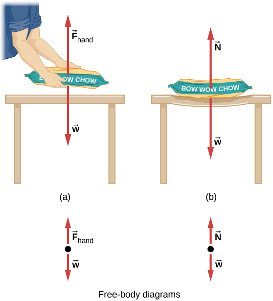
We must conclude that whatever supports a load, be it animate or not, must supply an upward force equal to the weight of the load, as we assumed in a few of the previous examples. If the force supporting the weight of an object, or a load, is perpendicular to the surface of contact between the load and its support, this force is defined as a normal force and here is given by the symbol [latex]\overset{\to }{N}.[/latex] (This is not the newton unit for force, or N.) The word normal means perpendicular to a surface. The normal force can be less than the object’s weight if the object is on an incline, as you will see in the next example.
Misconception Alert: Normal Force (N) vs Netwon (N)
In this section we have introduced the quantity normal force, which is represented by the variable N. This should not be confused with the symbol for the newton, which is also represented by the letter N. These symbols are particularly important to distinguish because the units of a normal force N happen to be newtons (N). For example, the normal force N that the floor exerts on a chair might be N=100 N. One important difference is that normal force is a vector, while the Newton is simply a unit. Be careful not to confuse these letters in your calculations! You will encounter more similarities among variables and units as you proceed in biomechanics. Another example of this is the quantity work (W) and the unit watts (W).
credit: Paul Peter Urone, Roger Hinrichs
Example: Weight on an Incline
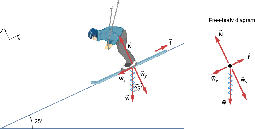
Consider the skier on the slope in Figure 4.22. Her mass including equipment is 60.0 kg.
(a) What is her acceleration if friction is negligible?
(b) What is her acceleration if friction is 45.0 N?
Strategy
This is a two-dimensional problem, since not all forces on the skier (the system of interest) are parallel. However, the approach we have used in two-dimensional kinematics also works well here:
First, choose a convenient coordinate system and project the vectors onto its axes, creating two one-dimensional problems to solve. The most convenient coordinate system for motion on an incline is one that has one coordinate parallel to the slope and one perpendicular to the slope. We can use x and y for the parallel and perpendicular directions, respectively.
Next, we can resolve the forces into the x and y components. Regarding friction, it is drawn in opposition to motion (friction always opposes forward motion) and is always parallel to the slope, [latex]{w}_{x}[/latex] is drawn parallel to the slope and downslope (it causes the motion of the skier down the slope), and [latex]{w}_{y}[/latex] is drawn as the component of weight perpendicular to the slope.
Lastly, we can consider the separate problems of forces parallel to the slope and forces perpendicular to the slope. In this case, it is the components parallel to the slope we are interested in, since there is no motion perpendicular to the slope (the skier is not moving up or down relative to the surface of the slope).
Solution
Using right angle trigonometry we can find the magnitude of the component of weight parallel to the slope as:
[latex]{w}_{x}=w\,\text{sin}\,25\text{°}=mg\,\text{sin}\,25\text{°},[/latex]
and the magnitude of the component of the weight perpendicular to the slope as:
[latex]{w}_{y}=w\,\text{cos}\,25\text{°}=mg\,\text{cos}\,25\text{°}.[/latex]
a. Neglecting friction.
Since the acceleration is parallel to the slope, we need to only consider forces parallel to the slope. (Forces perpendicular to the slope add to zero, since there is no acceleration in that direction.) The forces parallel to the slope are the component of the skier’s weight parallel to slope [latex]{w}_{x}[/latex] and friction f. Using Newton’s second law, with subscripts to denote quantities parallel to the slope,
[latex]{a}_{x}=\frac{{F}_{\text{net}\,x}}{m}[/latex]
where [latex]{F}_{\text{net}\,x}={w}_{x}-mg\,\text{sin}\,25\text{°},[/latex] assuming no friction for this part. Therefore,
[latex]\begin{array}{cc} {a}_{x}=\frac{{F}_{\text{net}\,x}}{m}=\frac{mg\,\text{sin}\,25\text{°}}{m}=g\,\text{sin}\,25\text{°}\hfill \\ (9.80\,{\text{m/s}}^{2})(0.4226)=4.14\,{\text{m/s}}^{2}\hfill \end{array}[/latex]
is the acceleration.
b. Including friction.
We have a given value for friction, and we know its direction is parallel to the slope and it opposes motion between surfaces in contact. So the net external force is
[latex]{F}_{\text{net}\,x}={w}_{x}-f.[/latex]
Substituting this into Newton’s second law, [latex]{a}_{x}={F}_{\text{net}\,x}\text{/}m,[/latex] gives:
[latex]{a}_{x}=\frac{{F}_{\text{net}\,x}}{m}=\frac{{w}_{x}-f}{m}=\frac{mg\,\text{sin}\,25\text{°}-f}{m}.[/latex]
We substitute known values to obtain
[latex]{a}_{x}=\frac{(60.0\,\text{kg})(9.80\,{\text{m/s}}^{2})(0.4226)-45.0\,\text{N}}{60.0\,\text{kg}}.[/latex]
This gives us
[latex]{a}_{x}=3.39\,{\text{m/s}}^{2},[/latex]
which is the acceleration parallel to the incline when there is 45.0 N of opposing friction.
Discussion
Since friction always opposes motion between surfaces, the acceleration is smaller when there is friction than when there is none. In part a) we saw that the mass of the object in the numerator and denominator cancelled out. So, it is a general result that if friction on an incline is negligible, then the acceleration down the incline is [latex]a=g\,\text{sin}\,\theta[/latex], regardless of mass.
As discussed previously, all objects fall with the same acceleration in the absence of air resistance. Similarly, all objects, regardless of mass, slide down a frictionless incline with the same acceleration (if the angle is the same).
Resolving Weight Into Components
When an object rests on an incline that makes an angle [latex]\theta[/latex] with the horizontal, the force of gravity acting on the object is divided into two components: a force acting perpendicular to the plane, [latex]{w}_{y}[/latex], and a force acting parallel to the plane, [latex]{w}_{x}[/latex] (Figure 4.23). The normal force [latex]\overset{\to }{N}[/latex] is typically equal in magnitude and opposite in direction to the perpendicular component of the weight [latex]{w}_{y}[/latex]. The force acting parallel to the plane, [latex]{w}_{x}[/latex], causes the object to accelerate down the incline.
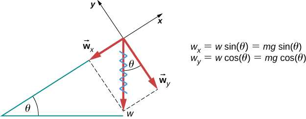
So, when resolving the weight of the object into components we can use the following equations to determine the magnitude of the x and y components of weight (assuming [latex]\theta[/latex] is the angle relative to the horizontal):
[latex]{w}_{x}=w\,\text{sin}\,\theta =mg\,\text{sin}\,\theta[/latex]
and
[latex]{w}_{y}=w\,\text{cos}\,\theta =mg\,\text{cos}\,\theta[/latex]
Instead of memorizing these equations, we can also determine them from reason. To do this, we draw the right angle formed by the three weight vectors. The angle [latex]\theta[/latex] of the incline is the same as the angle formed between w and [latex]{w}_{y}[/latex]. Knowing this property, we can use trigonometry to determine the magnitude of the weight components:
[latex]\begin{array}{cc} \text{cos}\,\theta =\frac{{w}_{y}}{w},\enspace{w}_{y}=w\,\text{cos}\,\theta =mg\,\text{sin}\,\theta \hfill \\ \text{cos}\,\theta =\frac{{w}_{x}}{w},\enspace{w}_{x}=w\,\text{sin}\,\theta =mg\,\text{sin}\,\theta .\hfill \end{array}[/latex]
Tension
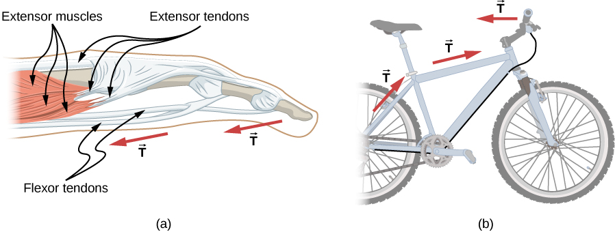
A tension is a force along the length of a medium; in particular, it is a pulling force that acts along a stretched flexible connector, such as a rope or cable. The word “tension” comes from a Latin word meaning “to stretch.” Not coincidentally, the flexible cords that carry muscle forces to other parts of the body are called tendons.
Any flexible connector, such as a string, rope, chain, wire, or cable, can only exert a pull parallel to its length; thus, a force carried by a flexible connector is a tension with a direction parallel to the connector. Tension is a pull in a connector. Consider the phrase: “You can’t push a rope.” Instead, tension force pulls outward along the two ends of a rope.
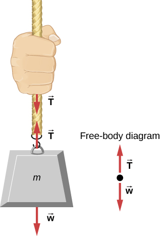
Consider a person holding a mass on a rope, as shown in Figure 4.24. If the 5.00-kg mass in the figure is stationary, then its acceleration is zero and the net force is zero. The only external forces acting on the mass are its weight and the tension supplied by the rope. Thus,
[latex]{F}_{\text{net}}=T-w=0,[/latex]
where T and w are the magnitudes of the tension and weight, respectively, and their signs indicate direction, with up being positive. As we proved using Newton’s second law, the tension equals the weight of the supported mass:
Thus, for a 5.00-kg mass (neglecting the mass of the rope), we see that
[latex]T=mg=(5.00\,\text{kg})(9.80\,{\text{m/s}}^{2})=49.0\,\text{N}\text{.}[/latex]
If we cut the rope and insert a spring, the spring would extend a length corresponding to a force of 49.0 N, providing a direct observation and measure of the tension force in the rope.
Flexible connectors are often used to transmit forces around corners, such as in a hospital traction system, a tendon, or a bicycle brake cable. If there is no friction, the tension transmission is undiminished; only its direction changes, and it is always parallel to the flexible connector, as shown in Figure 4.25.
Friction
Friction is defined a resistive force opposing motion or its tendency. Imagine an object at rest on a horizontal surface. The net force acting on the object must be zero, leading to equality of the weight and the normal force, which act in opposite directions. If the surface is tilted, the normal force balances the component of the weight perpendicular to the surface. If the object does not slide downward, the component of the weight parallel to the inclined plane is balanced by friction. Friction is discussed in greater detail later in this chapter.
Spring force
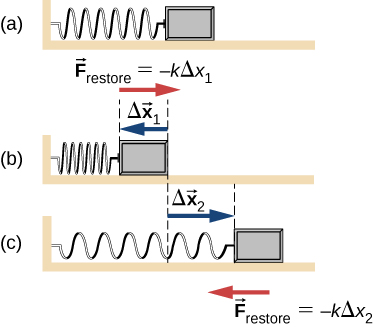
A spring is an object that has the ability to restore its shape, if deformed. To restore its shape, a spring exerts a restoring force that is proportional to and in the opposite direction in which it is stretched or compressed. This is the statement of a law known as Hooke’s law, which has the mathematical form
[latex]\overset{\to }{F}=\text{−}k\overset{\to }{x}.[/latex]
The constant of proportionality k is a measure of the spring’s stiffness. The line of action of this force is parallel to the spring axis, and the sense of the force is in the opposite direction of the displacement vector (Figure 4.29). The displacement must be measured from the relaxed position; [latex]x=0[/latex] when the spring is relaxed.
You will encounter principles related to springs and Hooke's Law in advanced biomechanics courses where they are used to examine forces in ligaments and tendons under stretch and also the force produced by elastic tubing during resistance training. For an example of these principles, stretch and compress springs in this activity to explore the relationships among force, spring constant, and displacement.
Example: What Is the Tension in a Tightrope?
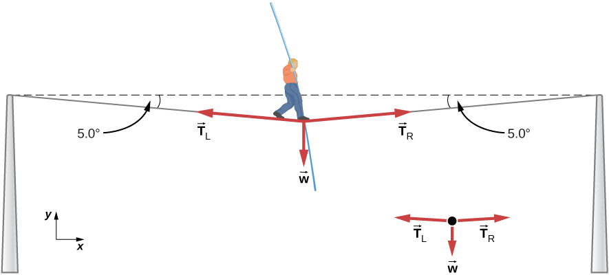
Calculate the tension in the wire supporting the 70.0-kg tightrope walker shown in Figure 4.26.
Strategy
As you can see in Figure 4.26, the wire is bent under the person’s weight. Thus, the tension on either side of the person has an upward component that can support his weight. As usual, forces are vectors represented pictorially by arrows that have the same direction as the forces and lengths proportional to their magnitudes. The system is the tightrope walker, and the only external forces acting on him are his weight [latex]\overset{\to }{w}[/latex] and the two tensions [latex]{\overset{\to }{T}}_{\text{L}}[/latex] (left tension) and [latex]{\overset{\to }{T}}_{\text{R}}[/latex] (right tension).
It is reasonable to neglect the weight of the wire. The net external force is zero, because the system is static. We can use trigonometry to find the tensions. One conclusion is possible at the outset—we can see from Figure 4.26 (b) that the magnitudes of the tensions [latex]{T}_{\text{L}}[/latex] and [latex]{T}_{\text{R}}[/latex] must be equal. We know this because there is no horizontal acceleration in the rope and the only forces acting to the left and right are [latex]{T}_{\text{L}}[/latex] and [latex]{T}_{\text{R}}[/latex]. Thus, the magnitude of those horizontal components of the forces must be equal so that they cancel each other out.
Whenever we have two-dimensional vector problems in which no two vectors are parallel, the easiest method of solution is to pick a convenient coordinate system and project the vectors onto its axes. In this case, the best coordinate system has one horizontal axis (x) and one vertical axis (y).
Solution
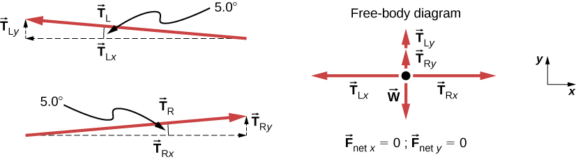
First, we need to resolve the tension vectors into their horizontal and vertical components. It helps to look at a new free-body diagram showing all horizontal and vertical components of each force acting on the system (Figure 4.27).
Consider the horizontal components of the forces (denoted with a subscript x):
[latex]{F}_{\text{net}\,x}={T}_{\text{R}x}-{T}_{\text{L}x}.[/latex]
The net external horizontal force [latex]{F}_{\text{net}\,x}=0,[/latex] since the person is stationary. Thus,
[latex]\begin{array}{ccc}\hfill {F}_{\text{net}\,x}& =\hfill & 0={T}_{\text{R}x}-{T}_{\text{L}x}\hfill \\ \hfill {T}_{\text{L}x}& =\hfill & {T}_{\text{R}x}.\hfill \end{array}[/latex]
Now observe Figure 4.27. You can use trigonometry to determine the magnitude of [latex]{T}_{\text{L}}[/latex] and [latex]{T}_{\text{R}}[/latex]:
[latex]\begin{array}{cc} \hfill \text{cos}\,5.0\text{°}& =\hfill & \frac{{T}_{\text{L}x}}{{T}_{\text{L}}},\enspace{T}_{\text{L}x}={T}_{\text{L}}\text{cos}\,5.0\text{°}\hfill \\ \hfill \text{cos}\,5.0\text{°}& =\hfill & \frac{{T}_{\text{R}x}}{{T}_{\text{R}}},\enspace{T}_{\text{R}x}={T}_{\text{R}}\text{cos}\,5.0\text{°}.\hfill \end{array}[/latex]
Equating TLx and TRx:
[latex]{T}_{\text{L}}\text{cos}\,5.0\text{°}={T}_{\text{R}}\text{cos}\,5.0\text{°}.[/latex]
Thus,
[latex]{T}_{\text{L}}={T}_{\text{R}}=T,[/latex]
as predicted. Now, considering the vertical components (denoted by a subscript y), we can solve for T. Again, since the person is stationary, Newton’s second law implies that [latex]{F}_{\text{net}\,y}=0[/latex]. Thus, as illustrated in the free-body diagram,
[latex]{F}_{\text{net}\,y}={T}_{\text{L}y}+{T}_{\text{R}y}-w=0.[/latex]
We can use trigonometry to determine the relationships among [latex]{T}_{\text{Ly}},{T}_{\text{Ry}},[/latex] and T. As we determined from the analysis in the horizontal direction, [latex]{T}_{\text{L}}={T}_{\text{R}}=T[/latex]:
[latex]\begin{array}{}\\ \hfill \text{sin}\,5.0\text{°}& =\hfill & \frac{{T}_{\text{L}y}}{{T}_{\text{L}}},\enspace{T}_{\text{L}y}={T}_{\text{L}}\text{sin}\,5.0\text{°}=T\,\text{sin}\,5.0\text{°}\hfill \\ \hfill \text{sin}\,5.0\text{°}& =\hfill & \frac{{T}_{\text{R}y}}{{T}_{\text{R}}},\enspace{T}_{\text{R}y}={T}_{\text{R}}\text{sin}\,5.0\text{°}=T\,\text{sin}\,5.0\text{°}.\hfill \end{array}[/latex]
Now we can substitute the values for [latex]{T}_{\text{Ly}}[/latex] and [latex]{T}_{\text{Ry}}[/latex], into the net force equation in the vertical direction:
[latex]\begin{array}{ccc}\hfill {F}_{\text{net}\,y}& =\hfill & {T}_{\text{L}y}+{T}_{\text{R}y}-w=0\hfill \\ \hfill {F}_{\text{net}\,y}& =\hfill & T\,\text{sin}\,5.0\text{°}+T\,\text{sin}\,5.0\text{°}-w=0\hfill \\ \hfill 2T\,\text{sin}\,5.0\text{°}-w& =\hfill & 0\hfill \\ \hfill 2T\,\text{sin}\,5.0\text{°}& =\hfill & w\hfill \end{array}[/latex]
and
[latex]T=\frac{w}{2\,\text{sin}\,5.0\text{°}}=\frac{mg}{2\,\text{sin}\,5.0\text{°}},[/latex]
so
[latex]T=\frac{(70.0\,\text{kg})(9.80\,{\text{m/s}}^{2})}{2(0.0872)},[/latex]
and the tension is
[latex]T=3930\,\text{N}\text{.}[/latex]
Discussion
The vertical tension in the wire acts as a force that supports the weight of the tightrope walker. The tension is almost six times the 686-N weight of the tightrope walker. Since the wire is nearly horizontal, the vertical component of its tension is only a fraction of the tension in the wire. The large horizontal components are in opposite directions and cancel, so most of the tension in the wire is not used to support the weight of the tightrope walker.
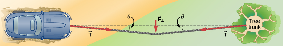
Continuing the advanced example from above, if we wish to create a large tension, all we have to do is exert a force perpendicular to a taut flexible connector, as illustrated in Figure 4.28. As we saw in Figure 4.27, the weight of the tightrope walker acts as a force perpendicular to the rope. We saw that the tension in the rope is related to the weight of the tightrope walker in the following way:
We can extend this expression to describe the tension T created when a perpendicular force [latex]({F}_{\perp })[/latex] is exerted at the middle of a flexible connector:
The angle between the horizontal and the bent connector is represented by [latex]\theta [latex]. In this case, T becomes large as [latex] \theta[/latex] approaches zero. Even the relatively small weight of any flexible connector will cause it to sag, since an infinite tension would result if it were horizontal (i.e., [latex]\theta =0[/latex] and sin [latex]\theta =0[/latex]).
For example, Figure 4.28 shows a situation where we wish to pull a car out of the mud when no tow truck is available. Each time the car moves forward, the chain is tightened to keep it as straight as possible. The tension in the chain is given by [latex]T=\frac{{F}_{\perp }}{2\,\text{sin}\,\theta },[/latex] and since [latex]\theta[/latex] is small, T is large. This situation is analogous to the tightrope walker, except that the tensions shown here are those transmitted to the car and the tree rather than those acting at the point where [latex]{F}_{\perp }[/latex] is applied.
Check Your Understanding
One end of a 3.0-m rope is tied to a tree; the other end is tied to a car stuck in the mud. The motorist pulls sideways on the midpoint of the rope, displacing it a distance of 0.25 m. If he exerts a force of 200.0 N under these conditions, determine the force exerted on the car.
Solution:
[latex]6.0\,×\,{10}^{2} \text{N}[/latex]
