
Chapter 4: Linear Kinetics, Force and Newton’s Laws of Motion
4.1 Forces
Authors: William Moebs, Samuel Ling, Jeff Sanny
Adapted by: Rob Pryce, Alix Blacklin
Learning Objectives
By the end of this section, you will be able to:
- Distinguish between kinematics and kinetics
- Understand the definition of force
- Identify simple free-body diagrams
- Define the SI unit of force, the newton
The study of motion is called kinematics, but kinematics only describes the way objects move—their velocity and their acceleration. Kinetics is the study of how forces affect the motion of objects and systems. It considers the causes of motion of objects and systems of interest, where a system is anything being analyzed. The foundation of kinetics are the laws of motion stated by Isaac Newton (1642–1727). These laws provide an example of the breadth and simplicity of principles under which nature functions. They are also universal laws in that they apply to situations on Earth and in space.
Newton’s laws of motion were just one part of the monumental work that has made him legendary (Figure 5.2). The development of Newton’s laws marks the transition from the Renaissance to the modern era. Not until the advent of modern physics was it discovered that Newton’s laws produce a good description of motion only when the objects are moving at speeds much less than the speed of light and when those objects are larger than the size of most molecules (about [latex]{10}^{-9}[/latex] m in diameter). These constraints define the realm of Newtonian mechanics. At the beginning of the twentieth century, Albert Einstein (1879–1955) developed the theory of relativity and, along with many other scientists, quantum mechanics. Quantum mechanics does not have the constraints present in Newtonian physics. While all of these theories have incredibly important applications, in biomechanics we focus predominantly on Newtonian mechanics, which will be the focus of this chapter.

Kinetics is the study of the forces that cause objects and systems to move. To understand this, we need a working definition of force. An intuitive definition of force—that is, a push or a pull—is a good place to start. We know that a push or a pull has both magnitude and direction (therefore, it is a vector quantity), so we can define force as the push or pull on an object with a specific magnitude and direction.
The push or pull on an object can vary considerably in either magnitude or direction. For example, a cannon exerts a strong force on a cannonball that is launched into the air. In contrast, Earth exerts only a tiny downward pull on a flea. Our everyday experiences also give us a good idea of how multiple forces add. If two people push in different directions on a third person, as illustrated in Figure 5.3, we might expect the total force to be in the direction shown. Since force is a vector, it adds just like other vectors. Forces, like other vectors, are represented by arrows and can be added using the familiar head-to-tail method or trigonometric methods.
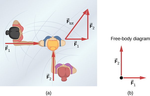
Figure 4.3 (b) is also our first example of something called a free-body diagram, which is a sketch showing all external forces acting on an object or system. The object or system is represented by a single isolated point (or free body), and only those forces acting on it that originate outside of the object or system—that is, external forces—are shown. (These forces are the only ones shown because only external forces acting on the free body affect its motion. We can ignore any internal forces within the body.) The forces are represented by vectors extending outward from the free body.
Free-body diagrams are very useful in analyzing forces in acting on an object or system. They are used extensively in biomechanics and in the application of Newton’s laws of motion. The following steps briefly explain how a free-body diagram is created.
Drawing Free-Body Diagrams – Strategy
- Draw the object under consideration. If you are treating the object as a particle, represent the object as a point. Place this point at the origin of an xy-coordinate system.
- Include all forces that act on the object, representing these forces as vectors. However, do not include the net force on the object or the forces that the object exerts on its environment.
- Resolve all force vectors into x– and y-components.
- If there is more than one object in the problem, draw a separate free-body diagram for each.
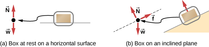
We illustrate this strategy with two examples of free-body diagrams in Figure 4.4. The terms used in this figure are explained in more detail later in the chapter.
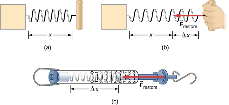
A more quantitative definition of force can be based on some standard force, just like distance is measured in units relative to a standard length (the meter). One possibility is to stretch a spring a certain fixed distance (Figure 4.5) and use the force it exerts to pull itself back to its relaxed shape—called a restoring force—as a standard. The magnitude of all other forces could then be considered as multiples of this standard unit of force. Many other possibilities exist for standard forces. Some other definitions will be given later in this chapter.
Let’s analyze force more deeply. Suppose a biomechanics student sits at a table, working diligently on their homework (Figure 4.6). What external forces act on them? Can we determine the origin of these forces?
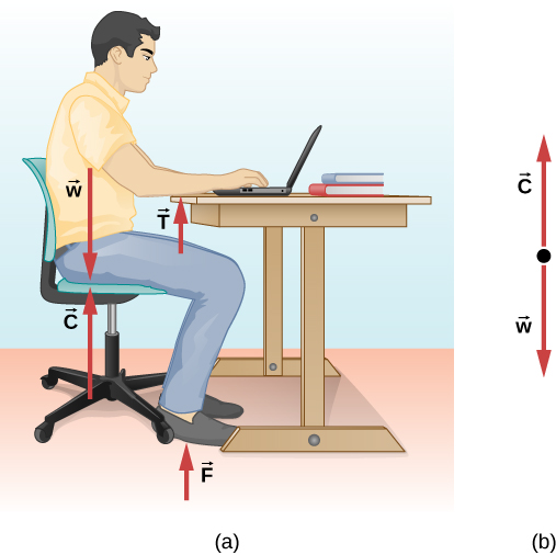
In most situations, forces are grouped into two categories: contact forces and non-contact (or field) forces. As you might guess, contact forces are due to direct physical contact between objects. For example, the student in Figure 4.6 experiences the contact forces [latex]\overset{\to }{C}[/latex], [latex]\overset{\to }{F}[/latex], and [latex]\overset{\to }{T}[/latex], which are exerted by the chair on his posterior, the floor on his feet, and the table on his forearms, respectively. Non-contact forces, however, act without the necessity of physical contact between objects. They depend on the presence of a “field” in the region of space surrounding the body under consideration. Since the student is in Earth’s gravitational field, he feels a gravitational force [latex]\overset{\to }{w}[/latex]; in other words, he has weight (we will define ‘weight’ later in this chapter).
In undergraduate biomechanics, weight (or the gravitational force) is generally the only non-contact force we encounter. In more advanced courses you may learn about the original of contact forces, such as how the student’s arm interacts with the surface of the table, or how tape sticks to a piece of paper. At the atomic level these are electromagnetic forces. However, in the context of Newtonian mechanics (and therefore biomechanics), the electromagnetic origin of contact forces is not an important concern.
Units of Force
The SI unit of force is called the Newton (abbreviated N) and is the force needed to accelerate a 1-kg object at a rate of 1m/s2. That is:
1 N = 1kg*m/s2
An easy way to remember the size of a Newton is to imagine holding a small apple. It has a weight of about 1 N. More specifically, a small apple has a mass of about 100g. In later sections we will learn the relationship between mass and force, as well as the difference between mass and weight, which will put the units of force in more context.
TAKE-HOME EXPERIMENT: FORCE STANDARDS
To investigate force standards and cause and effect, get two identical rubber bands. Hang one rubber band vertically on a hook. Find a small household item that could be attached to the rubber band using a paper clip, and use this item as a weight to investigate the stretch of the rubber band. Measure the amount of stretch produced in the rubber band with one, two, and four of these (identical) items suspended from the rubber band. What is the relationship between the number of items and the amount of stretch? How large a stretch would you expect for the same number of items suspended from two rubber bands? What happens to the amount of stretch of the rubber band (with the weights attached) if the weights are also pushed to the side with a pencil?
(credit: Paul Peter Urone; Roger Hinrichs)
